Dead Air, a 16oz combat bot
January 2013

It's been a long time since I made an ant weight (16oz) combat robot. It was 2004 when Thrasher was built. That bot was pretty awesome then but is unable to withstand the powerful KE weapons on so many robots today. Unprotected wheels, thin aluminum and polycarbonate are just not enough. But I did not intentionally start out to make yet another ant bot. Here's the story of how it slowly came into existence.
What I really wanted to do was create a new electric flipper weapon for a 12 or 30 pound bot that didn't use a flywheel. A few months ago I did some experiments to see if a flipper weapon could be made using a large capacitor to store energy and a motor to actuate the flipper. The idea was to charge a capacitor to some voltage far above the motors nominal rating then dump all the energy into the motor to create large amounts of torque for the few milliseconds required to flip an opponent... without blowing up the motor. I did the experiments small scale to make things easier and cheaper. Bascally the mechanics of it was just a motor geared down driving a crank shaft hooked to a pivioting lever which was the flipper weapon. Dumping 60 volts from an 11,000 uF capacitor into a 24 volt motor worked pretty well as shown in the video below.
At this point I wondered if I could tension a spring on the retract-stroke and release it during the power stroke thus adding the stored spring energy to the remaining capacitor energy. This actually worked even better than I thought. Video:
Clearly I was on to something, but there were some issues. The main problem seemed to be size and weight. Stuffing the mechanism and capacitor into a 1 pound bot would be a challenge. Also I'd need a switching power supply to get 60 or more volts for the capacitor. Scaling to 12 or 30 pounds would not help much either.
Then I started thinking that maybe I could just store all the energy in a spring. "Charging" the spring could be done with a standard gear-motor at low speed with sane voltages and currents. Unlike a flywheel, once the spring was "charged" it wouldn't need any power to maintain its stored energy.
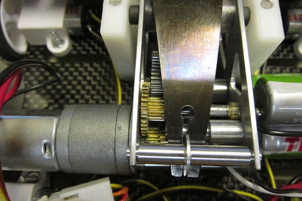
The only issue was how to do the spring release. The motor needs to tension the spring then at some point let go of it. 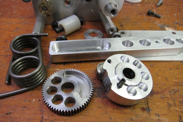 Eventually I realized that all I needed was to couple the drive gear to the crank with a pin and slot arrangement. A slot in the drive gear could push a pin in the crank to tension the spring but as soon as the top of the stroke was reached the spring would pull the crank away from the drive pin and be free to release as fast as it could go. See photo on left.
The spring pin in the aluminum crank disk mates with the milled pocket in the drive gear. This allows the crank disk to overrun the drive gear for almost 120 degrees. The round holes are for weight reduction.
I ordered several different torsion springs from McMaster and finally decided on a pair that provided about 20 in-lb torque (on left in photo above).
Another issue was stopping the motor just before top of stroke and holding position so the flipper can be fired by running the motor again. I cut out a notch in the crank disk for a one-way pawl. This turned out to be unnecessary since there was plenty of friction and little force at that point in the cycle. I used a small microswitch to detect the stopping point. Here's a demo video of this version.
While this was better than the capacitor version it was still a bit heavy and wide due to the pair of torsion springs. One refinement I made was to eliminate the one-way pawl and microswitch. The pawl was useless so taking it out was a no brainer. The limit switch took more thought. I had an idea that maybe a microcontroller could monitor the motor current and detect when to stop the motor. I got lucky. The current dropped significantly just before the optimum stopping point. See scope photo below.
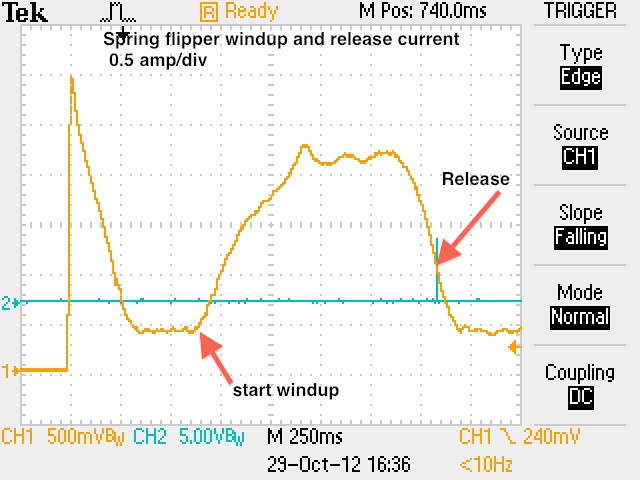
Monitoring motor current to find the stopping point worked very well. I built an small moble chassis to carry the the weapon, used a Pololu Baby Orangutan robot controller for the brains and did some testing. The flipper worked great but the bot itself kind of sucked. Also I still was not happy with the weight and width of the weapon. The torsion springs made it too wide. At this point I began thinking of using a flat piece of steel and a spring. I could custom design its size and rate. Instead of it being coiled up on either side of the flipper it could be placed over the top and take up very little space. But there were issues of winding and releasing... until one day I stumbled on this video on youtube. 450 g Jännä improved . 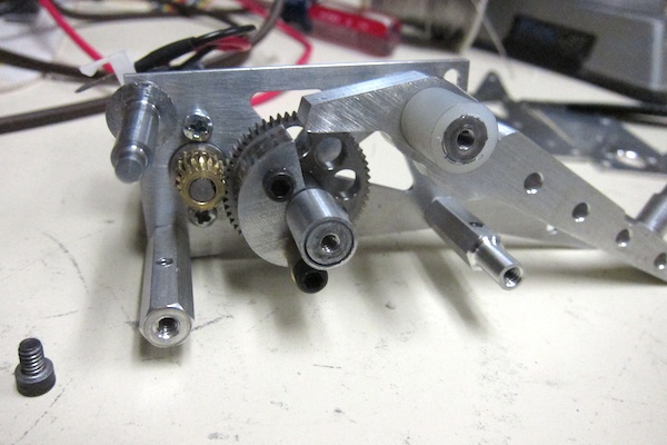 He used a cam to tension his coil spring but it would also be perfect for a flat leaf spring. Another advantage of a cam is I can make the lift profile exponential so the rate of lift slows down as the spring tension increases. That should make the motor current fairly constant. Sadly there is a disadvantage. Friction. The cam must be well lubed or bad things will happen. Aluminum on aluminum is suboptimal.
On the left is my version of the cam flipper mechanism with the right side and flat spring removed. The cam is screwed to the drive gear. This was taken before I added an extra 2.4:1 reduction gear between the motor and cam drive gear. I had to do that after I discovered the gears in the motor will self destruct if anything binds - like lack of lube on the cam. I also added current limiting in software.
At some point I had to design and fabricate a flat spring. I ordered several sheets of 1095 steel in different thicknesses from McMaster-Carr. This is a high carbon steel perfect for making springs. Once a spring is cut and shaped it must be heat treated by heating to 1475 degrees F then quenching in oil. Next it's tempered at 650 degrees F and turns a kind of bluish color. Then you have a spring. I used my beam deflection calculators, spring energy and flipper calculator to determine the dimensions by trial and error. The final version is .75" wide and .040" thick and about 3 inches of active spring length. The tapering distributes the bending more evenly over the length of the spring. It has almost 70 in-lb of torque when fully bent. Since the torque drops to zero at the end of travel I had to use 1/2 that value in the flipper performance calculations.
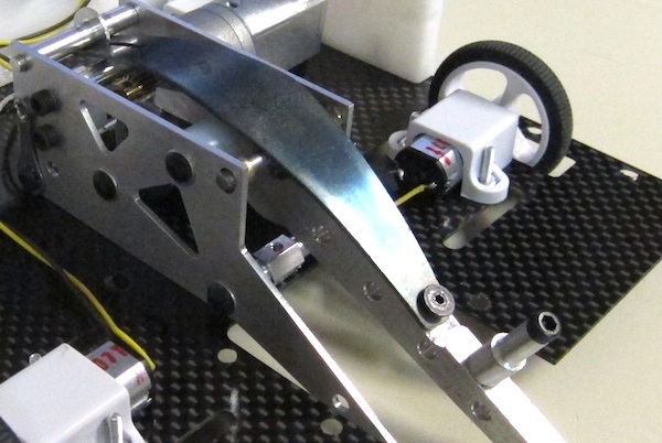
Here's a complete spring flipper attached to the robot. This is an early version. The final version cuts off the aluminum flipper and extends the spring all the way down. The spring is both energy storage and flipper paddle.
Here's a view of the extra gearing I had to add to keep the motor gear box from self destructing. The motor is a Pololu 154:1 gear motor and the pinion has 18 teeth. The cluster gear has 34 and 14 teeth. The cam drive has 60 teeth. All are module .4 metric gears except the 34 tooth which is 64 pitch. Why? That's what gear rod stock I had on hand and, yes, they do mate quite well. Probably a sign of the apocalypse.
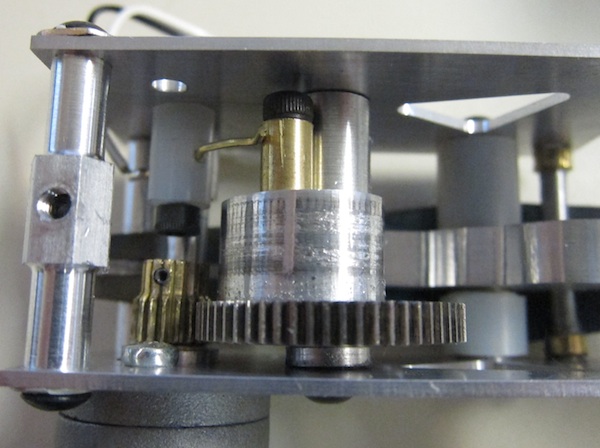
So, how does it know when to stop? The cam mechanism did not have a nice clean change of current to give the controller a clue about stopping even after I filed a flat spot on the cam. So, I had to do it in hardware. On the left you see a brass wire touching a brass cylinder. The brass cylinder is attached to the cam. When that contact wire touches the cyclinder it signals the controller to stop the motor.
Here's a demo video of the proof of concept version.
There was one major problem with the design in the above video. There is no end-of-travel stop on the flipper. When fired with no load there is a lot of overshoot and cam follower tends to hit the low part of the cam with such force it destroys the motors gearbox. Pololu then rings up yet another $20 sale. I added a 1/8 inch diameter piece of piano wire across the top of the flipper to limit overshoot.
Ok, I've got a pretty good weapon that can be scaled to 12 and 30 pound bots. What next? Since this thing weighs under 4 oz and can launch 1 pound objects I had a strong desire to build an ant class bot around it. So began phase two.
In the past I've favored bots that run upright or inverted so I don't have to do anything special when it gets flipped over. This involves making the top and bottom identical and/or the front and rear mirror images. In the case of spinning weapons you need to reverse the rotation when inverted. In the case of Overthruster I put flippers on both ends powered by a single flywheel. Unfortunately this spring flipper design isn't compatible with any sort of invertability. Bummer. However, it can serve double duty as a self-righting mechanism by firing when inverted and flipping itself 180 degrees. This is the approach I took.
Initially I built a prototype (photo left) using .093 and .063 polycarbonate sheets for the top and bottom and made the sides from ABS on my UP! 3D printer. This turned out to be 0.8 oz over-weight so I switched to .033 thick carbon fiber sheets I got from McMaster Carr. The top and bottom pieces were cut on a CNC milling machine with a 1/8 inch carbide end mill. (5000rpm, 13ipm, mist coolant)
The 3D printed side pieces are strong but very light due to the honeycomb-like interior structure. I hope they will stand up to abuse from various destructive weapons they will encounter. If they don't at least it's easy to make replacements. They have 0.1 inch diameter holes in the edges to accept #4 self-taping screws designed for plastic.
The motors are 50:1 gear motors from Pololu driving 1.25 inch Pololu wheels. Power and traction seem exceptionally good. I milled out around three sides of the motor mounting point to create a crude spring suspension. This may reduce shock and help prevent motor and wheel damage. We shall see.
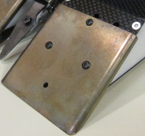
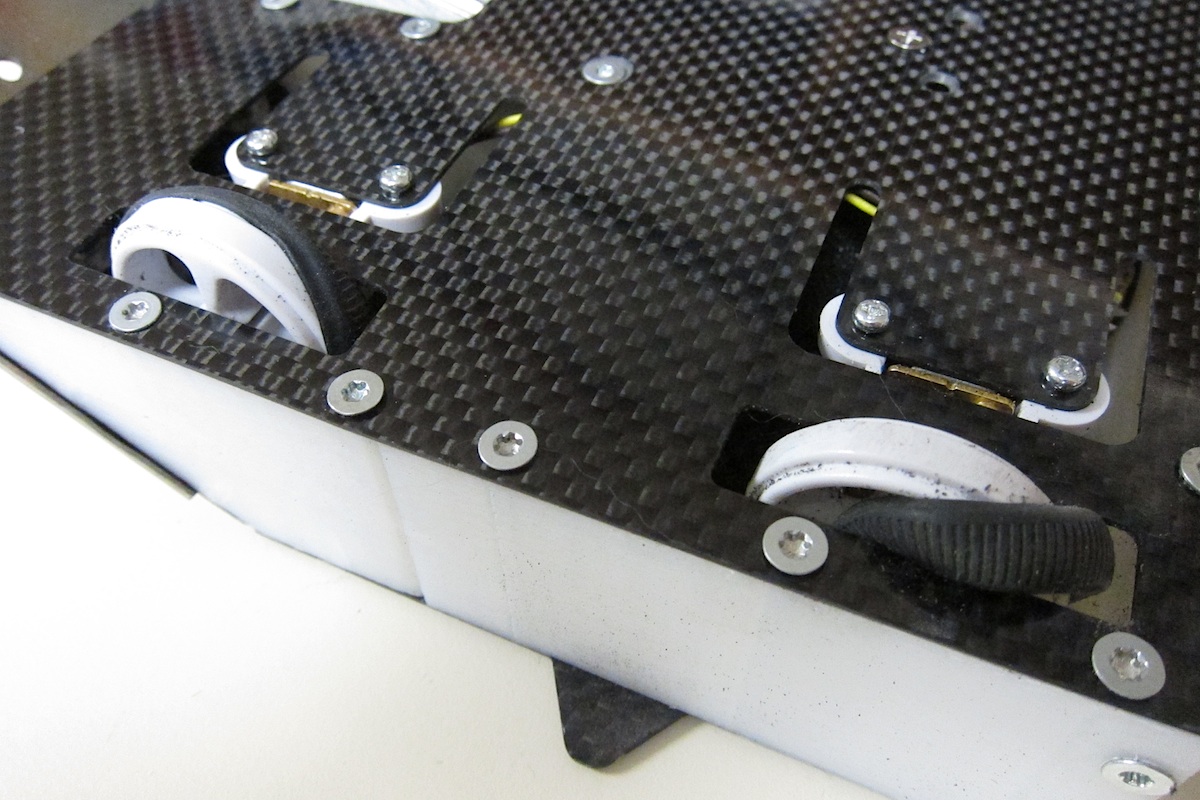
The wedges are made from .025 inch thick 1095 steel that I heat treated exactly like the flipper spring. They are attached to the bot with custom made standoff flanges riding in slots so they can slide up and down to maintain perfect contact with the floor. Since they slide upward when resistance is encountered they will ride up and over floor irregularities like my smart wedges. The common hinged wedge will dig in instead.
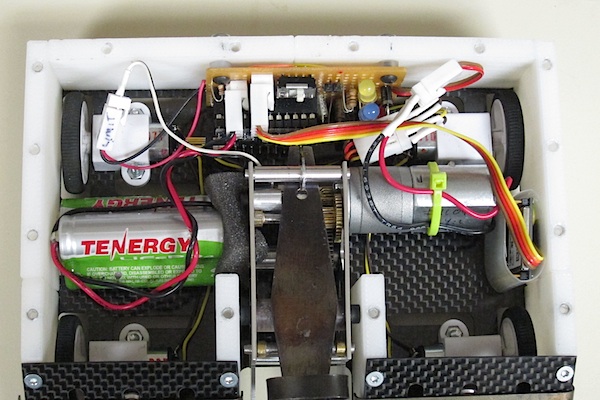
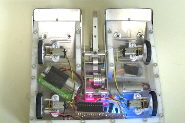
Here's the electronics. It's powered by three 3.3 volt, 450mAh LiFePO4 AA size batteries I picked up at Frys. They are glued together and held down with heavy duty double sided foam tape. The controller is a Pololu Baby Orangutan plugged into a piece of Radio Shack perf board which has various parts to interface with the spring tensioning motor and XBee 2.4 ghz radio (on the right). The slide switch controls power on/off and LEDs indicate status. The controller was programmed in C using avr-gcc on a Mac using Xcode as the editor.
A demo video of the final version. Spring tensioning is slow due to Pololu not having in stock the motor I really wanted to use.
I'm taking this bot to its first fight at Robot Battles 46 in Chattanooga on Jan. 26, 2013 to test the holding power of heavy duty double sided foam tape.
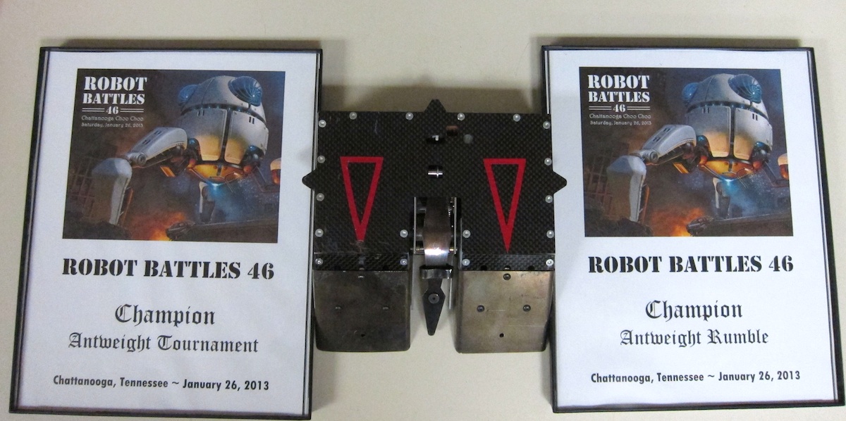
Robot Battles 46
Dead Air lost its virginity at RB46 in Chattanooga TN last weekend. There were 13 beetle weights but only 4 ant weights registered and of those 4 I only considered "Green Reaper" any threat. "Good Will" was a converted R/C toy bought for a dollar at Goodwill. "Last Resort" was built in an hour at the site from foam core and a few other bits and pieces including a brushless motor driving a flail. "Green Reaper" by Patrick Becker was a pretty decent bot with a good wedge and a small saw designed cut the underside of opponents as they went up the wedge. We got a nice demonstration of how that works when it took out Last Resort by cutting into his brushless weapon motor controller and set the bot on fire. Video here. Foam core makes for poor armor. Anyway, Dead Air had no problem defeating all of them. I quite enjoyed using the flipper to launch them into the push-out.
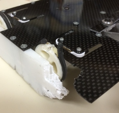
Since there were so few ants, the rumble was staged with all the bots that still worked in the arena at once. Last bot in each weight class still in the arena and/or running were declared winners. The fighting started and I was pleased to be able to push around and flip over some 3# beetles. Eventually Dead Air got pushed into the spinning sandpaper disk of death arena hazard. This is when I got schooled about Dead Airs problems. The rubber tread of one side came off the wheels and jammed in the wheel slot! It still moved a little but at that point I mostly just tried to stay away from the push out. Then Dead Air got into the hazard again an lost the tires on the other side. He could only wiggle a little at this point. Eventually the beetles finished killing off each other and Dead Air was the last ant still in the arena so received the WIN! Yea!
What I learned: Pololu tires will come off the wheel if too much lateral force if applied. The tires need to be glued on. But, they are silicone rubber and I have been unsuccessful in finding an adhesive that works with them. So, I've been experimenting with 3D printing my own wheels and using urethane belting material for the tread. It works but the traction is 40% less than the original tires so I need to do more work.
Here's a video about the wheels.
Feb. 9, 2013
Wheels, the final solution (I hope)
 I ordered various rubber items from McMaster-Carr for evaluation as tires. I hoped to find an o-ring with traction equal to the silicone tires from Pololu. I conducted traction tests by installing the tires and pulling the bot sideways across my work surface with a spring scale.
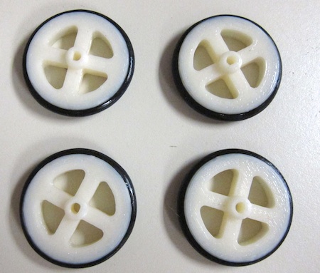
Silicone o-rings (durometer A70) were no better than the urethane belting material. Natural rubber cord was even worse. But there was a standout winner among the group. Soft Buna-N o-rings with a durometer of A50! These things are quite soft and have traction equal to the Pololu silicone tires. Unfortunately their softness lets them roll out of the wheel groove with moderate lateral force. But, unlike silicone rubber tires, super glue will bond to them so I just ran a bead around both sides to hold them securely.
Here's a link to the stl file required to 3D print the wheels. They fit 3mm D shaft motors. They are designed for 15/16" ID, 1 3/16" OD, 1/8 inch O-Rings. I used Mcmaster-Carr part # 2418T168. Finished diameter is 1.25 inches. Click here to download.
Aug. 31, 2014 Dragon*Con Robot Microbattles
 At this event Dead Air encountered the opponent we feared most, the horizontal spinner. He managed to beat a vertical spinner last January at Robot Battles 49 in Chattanooga but barely. A horizontal spinner is much worse for this design.
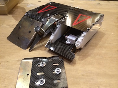
Dead Air is now known only by his first name after being dismembered by a 10,000 RPM horizontal spinner called DDT built and driven by Jamison Go. Vertical sides of 3D printed plastic are worthless against such an opponent. Even the 1095 spring steel wedges took some damage from the edge strikes. So, after this edcational experience I'm retiring Dead and will proceed to work on something that might have a chance of surviving a DDT attack.
Not only did DDT destroy the tire and wheel but the motor is also totaled.
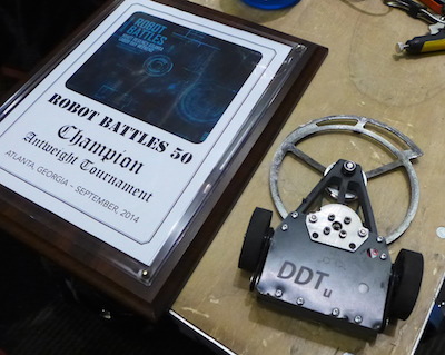
DDT went on to win the championship.
Hit Counter = 39923
Previous page: Death by Twinkies
Next page: iRoll
