iRoll
October 28, 2011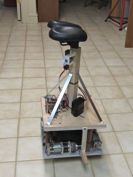
This page is about iRoll, an experimental ball balancer that I can ride. I designed and built it just because I wanted to see if I could. Apparently, I can. As far as I know it has no practical value other than entertaining easily amused YouTube viewers.
Riding it is easy. I control direction and speed by shifting my weight in the direction I want to go. I have little control over yaw. I can drag a foot to rotate myself but I need more practice doing that. So far the only injury is a slightly skined up left elbow. Now I know not to drive over small rocks on asphalt parking lots.
This is not a "how to" or construction article. I'm only going to cover a few highlights of the build and problems encountered. As usual I will provide schematics and source code in hope that someone may find them useful.
This project builds on what I learned from my analog radio controlled ball balancer robot, documented elsewhere on this site. More of the technical details are covered there. I mostly just needed to beef up the materials and power to a level that could support and move 150 pounds of nerd. I also finally found a good use for a bowling ball.
Here's a YouTube video of me riding the iRoll. Click here for an video of earlier testing.
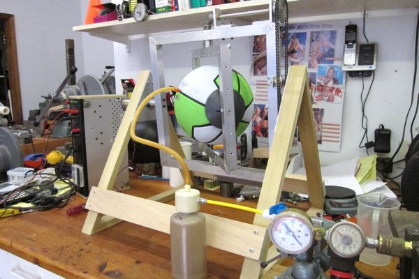
The ball drive
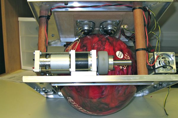 This is the drive system. There are 4 magnum 775 gear motors driving two inch Colson wheels friction coupled to a bowling ball. There are two motors for each axis and each pair are wired in series. The version shown on the left uses 4 ball transfers above the ball for support. Later I replaced the ball transfers with a single home made low profile caster wheel.
Initially I was going to use a size 5 basket ball for good traction and smooth ride. But, a few tests confirmed that an over-inflated basket ball was not anywhere near rigid enough. So, I bought a cheap 6 pound bowling ball. It's made of polyester and is very very slick. So slick in fact it didn't really work. Google found me an article about increasing the traction of bowling balls. It involved soaking them in the solvent MEK.
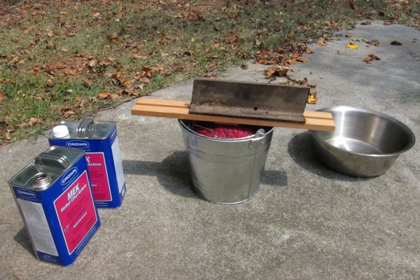
I went to Lowes and bought a bucket and a couple gallons of MEK. I soaked the ball for 30 minutes. Traction was greatly improved but still not really good enough to be 100% reliable on all floors. Sanding it helped a little more. Next I tried coating it with Rust-Oleum Truck Bed Coating spray. I applied 5 coats. Traction was now almost good enough. Unfortunately the truck bed coating is a little soft and will scrape off and mark the floor sometimes. I also tried coating the inside of a basket ball with Alumilite with a rotational casting rig. That did not work out well. So, the traction issue remains unresolved at this time.

This is the bottom frame. It's made of tig welded aluminum channel. The motors are mounted with 4 screws each in slots so I can adjust the tension between the 2 inch drive wheels and the bowling ball. The sides of the frame actually twist slightly with increased force creating a torsion spring to hold tension on the ball.

Here is the Sparkfun IMU gyro and accelerometer mounted on a homemade vibration isolator. This was found to be essential to prevent motor vibrations from severely interfering with proper operation of the accelerometers. The board is screwed to a block of steel. The steel block is glued to a 1/8 inch thick piece of rubber. The rubber is glued to a piece of polycarbonate which is screwed to the frame on top of yet another piece of rubber.
Note the IMU is near the outer edge. This is NOT the ideal place to put the IMU. When the iRoll rotates on the Z axis (spins) centripedal force biases the accelerometers making it tilt. It would be better to place the IMU near the center. I recently discovered this issue and will try to move the IMU to a better location.
Also shown is one of the tachometers. I used a small DC motor as a generator with a plastic wheel pressed on the shaft. The plastic wheel rides on the two inch drive wheel and generates a voltage proportional to the speed. The flexible plastic motor mount provides spring tension to hold contact with the wheel.

This is the low profile support caster wheel that replaced the 4 ball transfers. It runs much quieter but since the weight is concentrated on one wheel instead of 4 balls the force on the bowling ball surface is 4 times greater. I used a 4 inch turntable (lazy susan) and a machined aluminum wheel with ball bearing. The wheel is offset about 5/8 inch from center. Why not a cheap caster from Home Depot you ask? Weight capacity! The small ones can't take much weight and the ones that could were too big. The turn table shown here is rated at 300 pounds (2 x Me).
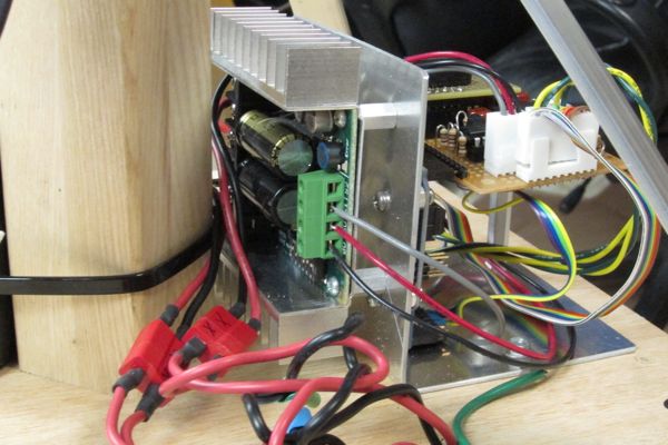
This is a view of the Sabertooth 2X25 motor controller from Dimension Engineering. It will control 2 DC brushed motors up to 25 amps and 24 volts. I'm issuing speed control commands via serial port at 9600 baud. The battery is six A123 cells in series for 20 volts @ 2200 MAH. Battery life is about 6 to 10 minutes per charge. A bigger battery is needed.

Here are the Arduino CPU and analog processor boards. This is a hybrid analog/digital system. The complimentary filters are analog op-amp based while the PID controllers for both motor speed regulation and balance are all software in the Arduino. There was an existing PID library for Arduino but I had to modify it. I also wrote a first order low pass filter library function. Yes, Arduinos can do DSP if the sample rate is slow enough. I'm sampling at 200Hz an using floating point.
The analog complimentary filters are almost identical to the ones used in the radio controlled ball balance bot except for one minor refinement. Originally the rate gyros were DC coupled all the way though the system. Any gyro DC offset drift seriously messed up true vertical calibration. Some days the bot would think 15 degrees was vertical and required recalibration! Stupid bot. So, I added a first order 0.16 Hz high-pass filter (see schematic C15, R57) in the gyro path to block DC and prevent this. Unfortunately doing that screwed up the delicate phase relationship with the accelerometers causing the combined frequency response to be un-flat. By trial and error I created a phase compensation network (see schematic C14,R47) for the accelerometer path to restore flat frequency response.

This is another view of the analog processor board. I ran out of space and had to add the 74HC4051 analog mux chip and 4 pots on the little daughter board.
Hit Counter 29782
Previous page: Dead Air, a 16oz combat bot
Next page: Polyathlon Robot
