Overthruster 30# Combat Robot
May 10 2008 - Progress so far
Last updated Nov. 19 2014
What the heck is an Overthruster you ask? It's a name I stole from the movie "Adventures of Buckaroo Banzai Across the 8th Dimension". In the movie the "Oscillation Overthruster" enabled travel to the 8th dimension. If my evil plan succeeds, opponents encountering this new bot will be launched into said 8th dimension or at least involuntarily moved a significant distance in one, two or three dimensions.

Prototype Overthruster bot
Flip-O-Matic weapon mounted in temporary wood chassis for testing. Flipper and wedges only implimented on one end during tests.
The bot is designed to compete in the 30 pound class at DragonCon Robot Battles. It will be 4 wheel drive and invertible. There will be flippers on both ends but only the front flipper is active. The symmetry is such that when inverted the rear becomes the front and what was the inactive rear flipper is now the active front flipper. The 6 inch Colson wheels will be driven by#25 roller chain and sprockets powered by a Dewalt drill motor coupled to a custom gearbox. I'm designing for 8 feet per second top speed.
Flip-O-Matic gearbox
 This bot carries my new Flip-O-Matic weapon described on the Flip-O-Matic page. In a nut shell, the flipper automatically fires when pressed against the opponent. There's no need to press a button on the remote at just the right time.
I built a completely new gear box with a 4 inch high profile and provisions for two output dog clutches so I can have independent flippers on the front and rear.
The overall ratio is 12.5:1 . The 0.5 inch output shaft turns at 2400 rpm. The flywheel on the right stores 400 Joules at 9000 rpm. It's powered by a 550 size 30,000 rpm R/C truck motor.
Click here to view a Quicktime move of the first test of the flipper. (Note: The flipped object only weighs about 12#)
May 16 2008
Progress has been made on the new clockwise dog clutches for the flip-O-Matic weapon system. The original design rotated counter clockwise which tended to unscrew the 1/2 inch shoulder bolt that served as the axle and retainer. To fix it I had to make new mirror image versions of the dog and holder disk. I made the dogs from 1018 steel instead of aluminum like the original which suffered minor warpage after only a few uses. I also thickened up the midsections of the dogs. They should not bend anymore.
This is a dog being cut from a block of 1018 steel with a CNC milling machine. The steel block is bolted to the aluminum fixture with 10-32 screws. The bit is a 1/2 inch end mill. Due to run-out and backlash issues some minor tweeking and cleanup was required with an air grinder, Dremmel tool and files.

This is the dog carrier disk being cut on the CNC mill.
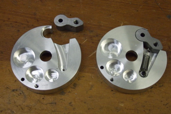
One dog and disk are finished, the other almost. The retaining spring is connected to the dog with a cotter pin that goes all the way through. The 3 round pockets on the lower left are to reduce weight.

Here's the complete dog clutch including the new 45 tooth, 12 pitch drive gear. This gear is made from 2024 aluminum. The original gear used in the Flip-O-Matic test video was made from much softer 6061 aluminum.

Here's the clutch on the old drive gear mounted in the weapon frame. Power from the dog clutch is coupled to the flipper through a 1/2 inch diameter shaft with commercial rod ends from McMaster Carr. One of the rod ends is left hand threaded so I can adjust the length slightly by turning the shaft. 1/4-20 bolts secure the rod ends to the dog and flipper.
Smart Wedges

Here are the new Smartwedges designed to retract when they encounter 1/4 inch "speed bump" hazards on the Robot Battles stage. They are CNC machined from 1/2 inch 6061 aluminum.
Not only do the wedges lift the opponent and guide him to the flipper, they also provide a solid footing on the stage to push against when the flipper fires. Very little force is felt in the frame or wheels.

A pair of 3/4 inch OD ball bearings are in the slot and provide very smooth low friction movement. When a hazard is hit the wedge moves up and back into the bots body. The bottom of the wedge can rise about 3/8 inch.
I tried it with a 1/2 inch slot and without ball bearings first but leverage and friction prevented it from working.
May 27 2008
Drive Gearboxes (27.8 : 1 ratio)
 Over the Memorial Day weekend I built a pair of gearboxes to couple the Dewalt drill motors to the chain and sprocket drive for the wheels. To save weight ABS plastic was used. I used a table saw to slice off 2 inch wide strips 12 inches long of 3/4 inch thick ABS. The blade heated up during the cut causing it to slightly melt the plastic. This stalled the saw. I had to wait a while for it to cool before finishing the cut. The 2 inch strips were cut to 4 inch lengths with my horizontal band saw.

After the blanks were cut I programmed the CNC mill to cut the various pockets and holes. I made both halves identical and symmetrical about the y axis. Only one CNC program was required.
Several manual operations were done afterward including taping, counter sinking and enlarging holes on one side to be clearance holes instead of tap holes.

Next up was the fun job of machining cluster gears from gear rod stock. I used 12, 16 and 40 tooth 32 pitch stock from McMaster Carr. The larger 40 tooth gears are pressed onto the shafts. The holes in the gears need to be about .001 to .002 smaller than the shafts. I had to be very careful when turning the shafts.
When pressing the gears on I used so much force the 3/16 diameter on the shaft end squished and became to large to go into the ball bearing. Back to the lathe to take off .0015...
Care and patience eventually paid off with a smooth running 27.8 : 1 gear box.
The intermediate shafts run on 3/16 ball bearings. The 3/8 output shaft runs on 3/8 nylon bearings and drives a 15 tooth sprocket.
Output shaft speed with no load should be about 650 RPM.
June 9th
 Wheels and sprockets
Since the bot body is 4 inches thick and needs to be invertable large wheels were required. I chose 6 inch Colson wheels which will give the bot an inch of ground clearance. Assuming I'd have weight issues (I always do!) I mounted them in the lathe an cut off a lot of plastic from the hub area.
I used #25 roller chain. The drive sprocket has 15 teeth and the wheel sprocket 30 for a 2:1 reduction ratio. Max wheel speed is about 325 rpm. This works out to 8.5 feet per second ground speed.


Next I had to machine the hub of the 30 tooth sprockets to a diameter suitable for press-fitting into the wheel hub. I cut the sprocket hub OD about 0.008" larger than the wheel hub ID. I also enlarged the sprocket hub ID to 3/4 inch to accept a 5/8 nylon bearing. A custom mandrel was made to hold the sprocket while turning down the outside diameter.
The hubs were coated with Loctite 609 retaining compound before being pressed into the wheel hubs. The mating surface is only 3/8 inch. Will it slip? I hope not. And lastly, I made two custom nylon bearings for the other side of the wheel hub.
I made 4 axles from 2024 aluminum stock. They are 5/8 inch diameter.
June 14th - 18th
Body Work and Drive Train
 The body/frame is 1/2 inch UHMW plastic. This is the first time I worked with it. UHMW is tough stuff but not very stiff. It can be cut with wood working equipment if tightly held. There seems to be a lot more friction and resistance than wood. It helped to spray coolant on the blade to prevent heating and melting of the plastic. I used a table saw and miter saw to cut the end pieces. They had 30 degree beveled edges. Once the saw blade was set at 30 degrees I ran strips of 5 inch wide UHMW through. I used a custom made pusher block to shield my hands and force the work down and into the blade. The saw slowed down under the load towards of each cut due heating I assume. Anyways, I got them all cut without loosing any appendages. The side panels were cut with the CNC mil.
 Now that the body panels are done it's time to assemble the chain drive. Note that the idler sprockets (see photo on right) allow the chain to be routed over or under the 15 tooth center drive sprocket. I had to do this because the left and right motors must be both run in the same direction due to the communtator timing advance on the DeWalt drill motors. If I had electrically reversed one motor there would be a 7% speed difference between left and right. So, one side has the chain running over the drive sprocket and the other side goes under.

 I needed a way to adjust chain tension so I cut a slot to allow the position of one of the idler sprockets to be adjusted.
Unfortunately the slot didn't provide quite enough range. No problem, I just chucked a 1.25 inch aluminum round in the lathe and made nifty shaft offset mount. The shaft on one side is is offset 3/16 from center. This was done on the lathe by off-setting the part in a 4 jaw chuck (only 2 used) then turning the offset.
The offset shaft combined with the slot provided plenty of adjustment range.

On the right you can see it's almost a bot. Eight screws and the frame/body will be done.
The UHMW to UHMW connections were made with 10-14 thread forming screws, part number 95893A364 from McMaster Carr.

Now it needs cover panels, batteries, and a controller.
June 20th

Today I added the 1/8 inch polycarbonate top and bottom covers.
With top and bottom covers the bot weighs 28.54 pounds. This is not good. I'll be spending lots of time shaving of an ounce here and there to keep it below 30 after adding batteries, the controller and chain guard.
June 26th
Controller board assembled and first movement
 Before starting the weight reduction phase I decided to complete the bot and fully test it so I'll know exactly how much weight needs to be removed. So, Today I built a new controller.
Controller
This is the same controller I designed for Invertabot several years ago. It's also been used in Trisector and Omegaforce 2.0. There are some minor problems with the design, mainly the traces in the H-Bridge circuit are too narrow to handle the current in some cases. During construction I augmented the high current traces with wire and solder. They should handle at least twice the load now.
 Chassis Wiring
I used Duratrax power connectors to wire the chassis. These are a buck each from Tower Hobbies. The Flip-O-Matic weapon motor is switched with a 40 amp automotive relay. The wiring is protected with a 40 amp ATC blade type automotove fuse.
Batteries
Since MaxAmps hasn't shipped my new A123 cells yet I had to stuff in a couple of 6 cell NiMH packs and hold them in place with orange duct tape.
Firmware code
The next task was adapting the controller firmware code (written in C) for Overthruster. I started with the code for Omegaforce 2.0 and removed and changed lines as required. Overall the code is simplier than for any bot I've built. Unlike all my previous bots, Overthruster does not need any position sensing! When flipped upside down the back becomes the front and the controls still work the same due to geometry only. Unlike Omegaforce, the brushed weapon motor is controlled with a relay and doesn't need any PWM generator to control an external brushless ESC. Also the weapon motor doesn't need to be reversed. Simple!
And, finally, on June 26, 2008 Overthruster MOVES!
June 27th
Testing and Video
Here's a video hosted on YouTube that shows me testing Overthruster
If for some reason the embeded video player above doesn't work, click here.
July 1
Weight Reduction Surgery
 Overthruster needs to loose some weight. Lets see where the flab might be. The weapon gearbox walls are much thicker than needed on the top and bottom edges. Also, the output gear is solid 1/4 inch 2024 aluminum. I attacked them with the milling machine, drilling eight 1/2 inch holes in the gear and thinning the case walls. That saved about 4 ounces.
 Ok, what else... how about the steel 30 tooth sprockets on the wheels? They weigh 4 porky ounces each! A nylon version should weigh a lot less. However, I could not find any suitable nylon sprockets at my usual sources so I decided to try making my own. Hey, I have a CNC mill, how hard could it be?
First I needed the tooth geometry specs. I found one Internet page with instructions on how to draw a sprocket tooth. Although it had a couple of errors I was able to get the job done with additional help from Machinerys Handbook. The CNC program was  pretty short and simple. 3 radius cuts then 12 degree radial step and repeat 29 times. I used a 1/8 inch end mill.
The end result was a nice looking nylon sprocket that weighed only 0.75 ounces. Since there are 4 of them I saved 13 ounces total.
Is nylon strong enough? Well, after reassembling the bot I used it to push around a 70 pound piece of rail road rail and an anvil. No problems so far.
July 2nd & 3rd
Chain Guards
With the first phase of the weight reduction complete I started work on the chain guards. I used .063 inch 6061-T6 sheet aluminum purchased at a local Metal SuperMarkets store.
 The design drawing was done in 2D with ViaCAD and printed 1:1 on an 11x17 sheet of paper. Some fiddling was required to get the dimensions just right. I bent several 1 inch wide test strips to verify and make small adjustments to the bend lines.
I glued the final drawing to the sheet aluminum with Elmers CraftBond spray adhesive and drilled all the holes. Then the band saw was used to cut out the part. Finally the metal brake was used to make the 4 bends. I made a 113 degree reference angle gage to make sure I got the angles right.

End result: Perfect fit! The chain guard also adds a lot of rigidity to the wheels and axles. They weigh 5 oz each.
July 16th
Pretty much done

Here it is after top and bottom lexan panel painting and engraving "Overthruster" on the chain guards. I left the top cover clear in the middle to show off the intimidating Flip-O-Matic gears/dog clutches. It weighs 29.88 pounds! Holy crap, it's still under-weight by almost 2 oz. Maybe I can squeeze in a super bright blue LED on the front.
August 17 - 19
Murphy's law invoked
 While showing the bot to a friend of mine on Sunday the Flip-O-Matic weapon quit working. The motor just stopped. WTF?! It's a simple motor switched with a relay. What could possibly go wrong? Well, the brushes could be totally burned up. Yep, the brush on the bottom came from the dead motor. The top one is new.
Why? My simple relay motor controller was too simple, that's why. The motor got full power from a dead stop when the relay closed and applied full battery voltage. Pulling 80 amps at startup, brilliant blue-white sparks flashed from the brushes. As the flywheel speed increased current gradually dropped to 5 amps (sometimes 10). While all this arcing and rapid acceleration of the flywheel was pretty cool and intimidating there was a price to pay. Repeated 80 amp surges fried the brushes until they got too short to reach the commutator. Instead of being a cheapskate I should have used a brushless motor and controller just like OmegaForce. Maybe someday I'll learn. (Edit Aug 2010: Finally replaced the unreliable brushed motor with brushless this year! )
I considered replacing the brushes but after taking a look at the totally black commutator I decided to replace the whole motor. I had a couple of spares on hand. Motor replacement required removal and complete disassembly of the Flip-O-Matic gearbox.
 While it was disassembled I decided to try to fix another problem - loose fit between bearing and flywheel shaft. The flywheel shaft is about .004 too small and it has way too much play in the ball bearing. This causes resonate vibrations which seem to increase the apparent friction in the system. Sometimes the full-speed current suddenly increases from 5 to 10 amps when the noise changes. I needed a shaft that was a nice close slip fit in the ball bearing. This was stock keyed 3/8 shafting that actually measured .371 diameter. Remembering a trick my Dad told me about I decided to try increasing the shaft diameter by coating it with brass then turning it down to the final diameter with the lathe. A few minutes with the oxy-acetylene torch, some brazing rod and flux got the brass on the shaft. The lathe turned it down to the proper diameter. And wow, what a difference. It runs smoother and pulls a steady 5 amps. But I'm not done yet. Remember the 80 amp surges that toasted my brushes? Gotta do something about that.
 Any normal human would order an ESC to run the weapon motor so he could slowly bring the speed up and not get the current surge. But I'm not normal, and I hate waiting on UPS. I'll just build something from parts on hand instead. On the left you see my homemade solution. It's MOSFET power switch that's pulsed on and off 900 times a second by my main bot controller. It's on 75% and off 25%. Counter intuitively, this knocks down the 80 amp surge to 35 amps and has little effect on top speed. Brush arcing is also greatly reduced and it weighs less than the relay it replaced. The "PC board" was made by placing tape over the areas I wanted copper then etching the copper clad board in Ferric Chloride.
August 20
Run time check
I charged the batteries and ran the bot continously with the weapon running until it quit working. Time: 6 minutes, 15 seconds. I'd like to see 10 minutes but this should be good enough. I watched some videos of past events with a stop watch. Last year OmegaForce was running only 3 minutes and 45 seconds total for all its one-on-one matches. Other videos show that 3 round matches seldom run longer than one minute total time. It takes an hour to fully charge the batteries so it's 10 minutes of charge for every minute run.
After the long run I opened the cover and checked the temperature of all the parts. Nothing was too hot to touch. This is good.
Next step, DragonCon Robot Battles Sept. 1, 2008.
DragonCon Robot Battles
Sept 1 2008
Overthruster did great at its Robot Battles debut. We won the 30# Robot Battles championship and the 30# Battle Royale! It handled well and the Flip-O-Matic worked exactly as expected. We fought and defeated Jaws, Dandelions Revenge, Uberclocker, Vorpal Bunny Fu-Fu and Scimitar. I drove Overthruster off the stage once due to the bot being hidden behind the giant body of Scimitar. I lost track of which end of the bot was "front". Other than that minor screw up everything went perfectly. The only service required was to charge the batteries between every other match. I didn't even have to take off the cover.
For a my full Robot Battles 2008 report click here.

Video: All of Overthrusters fights at Robot Battles 2008 except Battle Royale
January 2010
I bought a Casio EX-F1 high speed camera this month. It will shoot video at 300, 600 or 1200 fps for playback at 30 fps. Can you say "awesome slow motion"?
Here's Overthruster flipping a 30# test load at 300 framse/sec.
Overthruster on Ice
Modifications for 2010 Robot Battles
 New in 2010 is the brushless weapon motor that replaces the unreliable Trinity Monster Maxx 550 size brushed motor. It's more efficient and has a legit speed controller. The main bot controller now slowly ramps up the weapon RPM to reduce the inrush surge current to about 20 amps. The motor and controller also weighs a couple ounces less than the brushed motor and control relay. Win-win!

Deans connectors have replaced the crappy Tamiya/Molex connectors. These are said to handle 80 amps. The old Tamiya/Molex were only rated at 15. They tended to overheat and fail as an open circuit rendering the bot crippled or dead. After 4 failures I finally got a clue and visited the local HobbyTown USA and bought 10 pairs of Deans. Spent half a day replacing the connectors in both this bot and OmegaForce. Another advantage for Deans is they are reusable - wires can be unsoldered and replaced.

This is a tiny 2.4 ghz wireless analog video camera I decided to attach to the front panel of the bot. It looks out through a small hole.
If I don't get too much WiFi and Bluetooth interference and nobody pokes any destructive probulators in the hole I should be able to record the bots eye view of it's battles.

The new flippers are shaped to reduce weight and look more menacing. They were also moved slightly forward with spacers to improve trigger reliability.
They are made from oil-hardining 1/8 inch tool steel heat treated to spring temper.
The dark hole on the left is the video camera portal.
Now we are ready for Dragon*Con Robot Battles 2010 on Monday Sept 6th 2010!
Sep. 4 2014. New improved smart wedges! These will tolerate some uncut on the speed bumps.
Exhibition match. Overthruster fighting Spanky at Atlanta Maker Fair Oct. 5 2014.
Hit Counter = 51360
Last reset April 1 2012
Previous page: Analog Ball Balancer
Next page: Cube Quest Robot - 2007/8 "The Cubinator"
