RADAR Motion Sensor
April 9,2018
This page will explain how to connect an HB100 microwave motion sensor to an analog input on a microcontroller for short range obstacle detection on mobile robots.
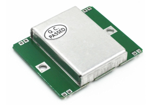
This is an HB100 microwave motion sensor module. It's a Doppler radar transceiver operating at 10.525 GHz. Datasheet here. These are widely available and inexpensive. But, the output signal is a very low level sine wave in the 1 to 50 millivolt range that cannot be directly connected to a microcontroller such as Arduino. The signal must be amplified and converted to a DC level suitable for connecting to microcontroller analog input.
Doppler Radar
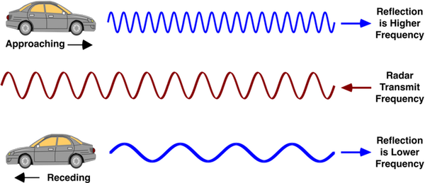
These motion detector modules depend on the Doppler effect. They bounce a 10.525 gigahertz signal off the target and output the difference between the transmitted and received signal frequencies. The difference frequency is called the Doppler frequency. It's proportional to the speed of the target, coming or going. Stationary objects will not produce any output. The Doppler frequency, fd, is calculated by: fd = 2*v*ft/c where v is velocity , ft is transmitted frequency and c is the speed of light. For 10.525 gHz, fd is 31.36 Hz per mph. For 24.125 gHz modules, fd is 72.26 Hz per mph.
The example circuit shown in the HB100 datasheet only produces a square(ish) wave to the Arduino to calculate frequency (speed) at distances up to 20 feet and does not provide any amplitude information. This is not useful if you want your indoor robot to avoid objects in its path. Anytime it moved, signals would bounce off walls and you'd get a readout of your robots speed relative to the wall. Since all the walls in a typical room would be within range it would be useless for detecting nearby obstacles (or sumo opponents).
The circuit below outputs a DC level proportional to the amplitude of the Doppler signal. Instead of a binary yes/no you get a range of signal strengths to use in making decisions. You can set thresholds in software. You can also change resistor R3 to increase of decrease the ultimate range to suit your application.
The ripple filter is designed for fast response. You can slow it down by increasing R4 or C3.
If you also need speed data you can connect op-amp pin 1 to an Arduino interrupt pin and measure frequency.
This circuit also works with the 24.125 gHz IPM-165 module and probably the CDM324.
The LMC6484 op-amp is a rail to rail type. Only 2 of the 4 sections are used. The extra sections can be used for a 2nd motion sensor. Click for datasheet.
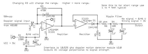
Note: Schematic updated 4/9/18. Added C4 and changed values of R1 and R2.
Here are some waveforms for reference. I produced these with a 100 Hz sine wave signal generator on the input.
Pin 1, op-amp first stage amplifier
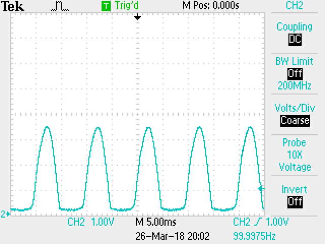
pin 7, op-amp rectifier output
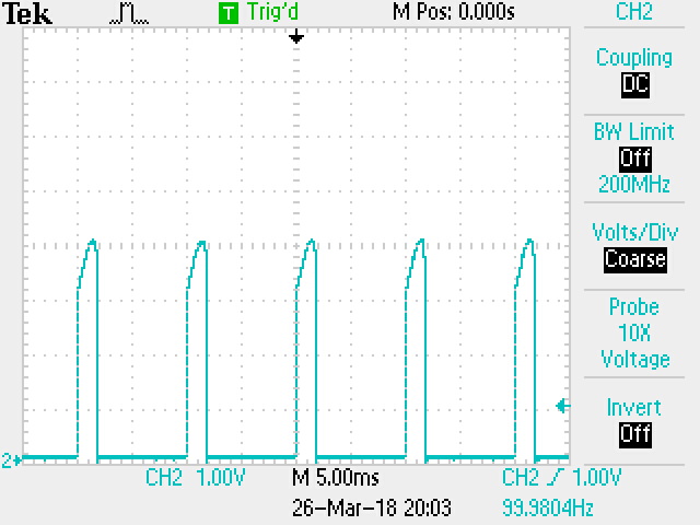
Ripple filter ouput
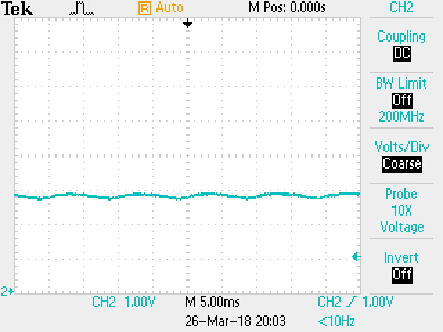
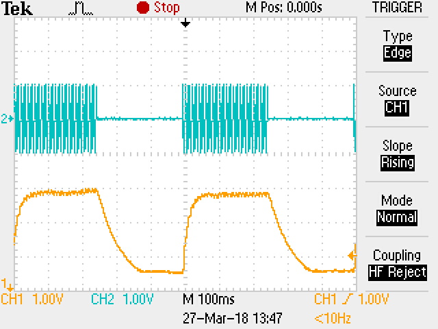
Ripple filter response
Top blue trace: 100 Hz input turned on and off at 2 Hz rate
Bottom orange trace: Ripple filter output (100ms/div)
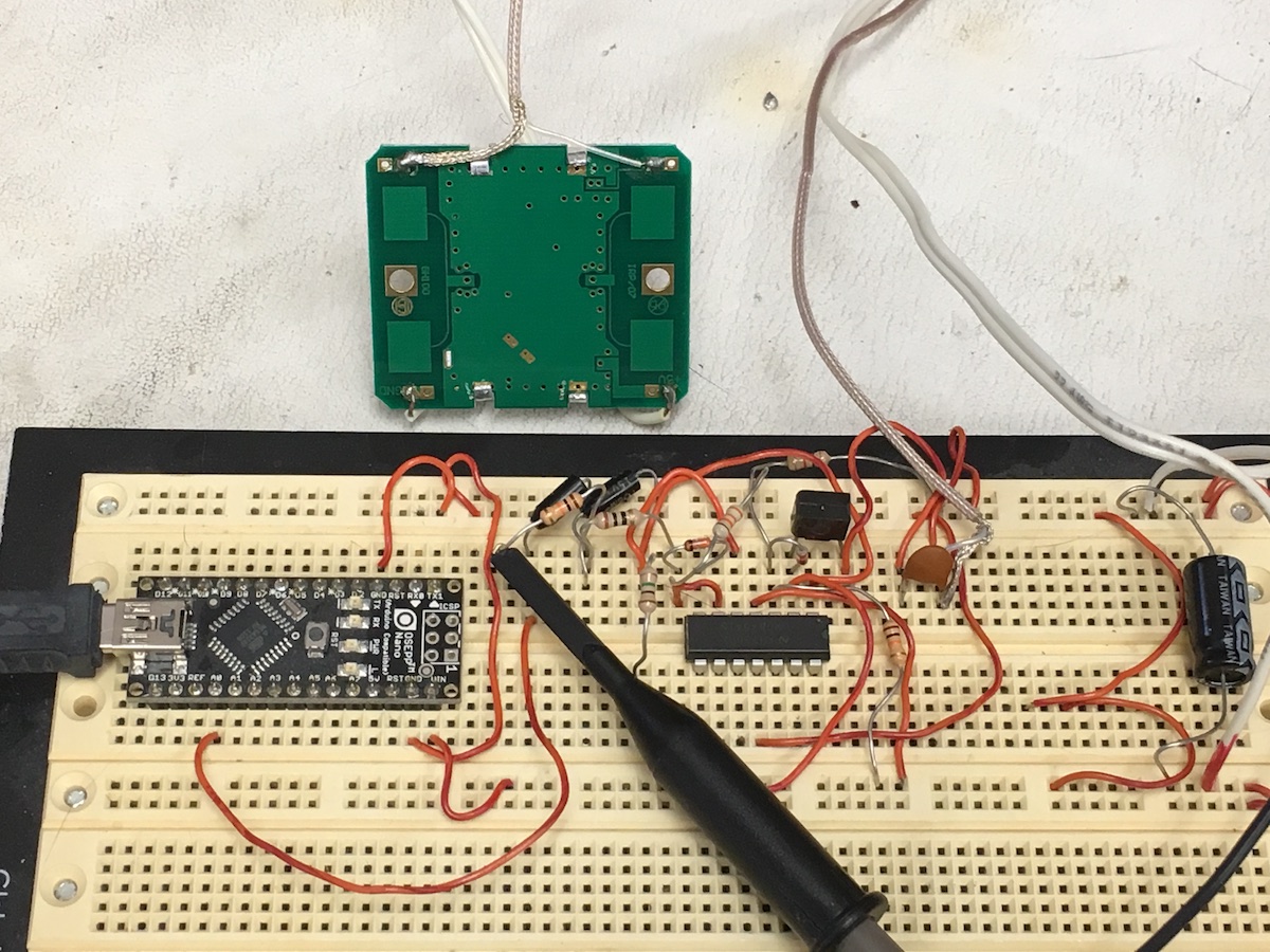
Protoboard version connected to an Arduino Nano
/* Arduino test code */
int analogPin = 0; // radar output connected to analog pin 0
int val = 0; // variable to store the value read
void setup()
{
Serial.begin(9600); // setup serial
pinMode(13,OUTPUT); //Indicator LED on pin 13
}
void loop()
{
val = analogRead(analogPin); // read the input pin
if(val > 180) digitalWrite(13,HIGH); //LED on if signal detected higher than 180
else digitalWrite(13,LOW);
Serial.println(val); // debug value
}
Hit Counter = 10283
Previous page: Suspending a Golf Ball with compressed air
Next page: Arduino Stuff
