Scary-Go-Round
June 15 2007 - progress so far
I've always disliked horizontal spinning combat robots. They seem to break themselves as much as the opponent and usually go flying across the arena after impact because of Newtons 3rd law. They are hard to control and would be difficult to keep on the stage at Robot Battles. Yet somehow I cannot resist the temptation to build a 30 pounder for DragonCon Robot Battles 2007. I guess it's the way they have a 360 degree defensive and offensive perimeter and the opponent has no choice but to directly attack the weapon.
Scary-Go-Round Project
What I have in mind is not going to be a common shell spinner nor will it be the classic full body spinner that can't spin and translate at the same time. No, this will be a different bot. The entire robot will both spin around it's axis and move across the combat surface in a controlled manner. It will not need to stop spinning in order to move around and attack the opponent. It will have holonomic drive and thus be able to move in any direction.
A recent Google search turned up this thing . Some call the technology "Melty Brain" for reasons unknown.

The first step towards the design was to verify that it was possible to achieve the combination spinning and translating by changing motor power alone. I built a simple 3 wheeled bot with photocells to control the motors. You can read all about it here.
 The experiment convinced me to go ahead and build a small radio controlled version to test ways of sensing the direction of the controller. The bot absolutely must have a stable reference heading to allow the operator to control the direction of movement. The experiment was a complete success. I used IR LEDs on the 900 mhz radio controller as a beacon for the bot to use as a directional reference. There were some problems with reflections from other objects in the room but I have since worked out a solution. More about that later.
A Model

Encouraged by the results so far I built a quarter scale model of the proposed 30 pound, 30 inch diameter Robot Battles version shown in the photo . The 3 flat black objects are leaf springs that store and then release energy during the collision making it elastic. A nice feature of this geometry is the opponent almost always gets hit in the side during the collision. Most bots do not have much protection there and it's usually a vertical side panel or wheel that gets hit.
By spinning the model clockwise by hand and shoving various quarter scale bot shaped objects into it I was able to get a good idea how Newtons 3rd law was going to screw up things. The results were as expected. The opponent flies off in one direction while the spinner stops spinning and goes nearly the same distance in the opposite direction. And yet I still feel compelled to build the full scale version for Robot Battles. That's just the way mad scientists are.
Energy
Robot Battles rules limit the perimeter speed of rotating weapons to 20 feet per second because combat is performed on a raised open stage. They don't want bot parts being ripped off and hurled into the audience at lethal speeds. (A reasonable policy) This limits the total kinetic energy available from a spinning 30 pound bot. In fact, for a 30 pound 30 inch diameter ring flywheel spinning at 152 rpm the stored kinetic energy is 250 Joules. This is the absolute maximum energy available. This provides the basis for other calculations such as power needed to spin up the bot in a reasonable time , distance opponents could be tossed and the rate values for the large springs at the ends of the arms.
The energy storage capacity of flywheels (in this case the whole bot) is determined by the mass distribution as well as weight and speed. A spinning bot with the mass evenly distributed has half the kinetic energy of one with all the mass at the perimeter. For best performance I need to design it with as much mass as far from the center as possible. ie: The batteries and motors go out on the arms. The light weight controller goes in the center.
Construction Begins
|
|
|
|


Ok, lets start out with the drive system. I need to spin the perimeter at a little less than 20 fps. If the wheels are on the perimeter they need to spin at an RPM that produces 20 fps at the tire surface. I€™m using 4 inch wheels so the circumference is Pi * 4 / 12 feet or 1.047 feet. It will move 1.047 feet per revolution so 20 / 1.047 is 19.09 rev/second or (19.09 * 60) = 1145 RPM max. But, the wheels will not be on the perimeter, they will be inset about 3 inches. The diameter of the bot is 30 inches and the wheels will spinning in a 24 inch circle.
To maintain 20 fps at the perimeter I need to reduce the wheel speed by: 24/30 = 0.8. 1145 * 0.8 = 916 rpm. I€™ll be using RC car motors that rev 21,000 rpm. 21000/916 = 22.9 gear ratio required. To make sure we do not exceed the 20fps rule the ratio should be a little higher.
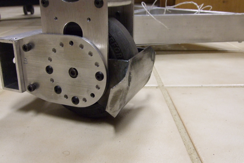
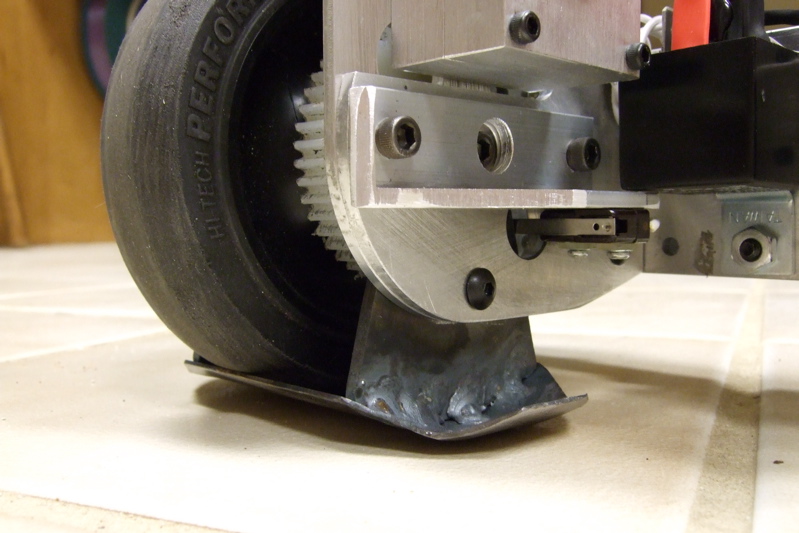
Using steel gear rod I built a 24:1 drive train as shown in the photos above and below. The nylon gear on the wheel is 24 pitch with 46 teeth I made with my CNC mill.
 |
 |
|

June 17, 2007
The frame has been assembled! I used Durafix rod with an oxy-acetylene torch to braze the 1x2 aluminum tubing. (see close-up). This was my first time using Durafix, the results are a little messy. I hope it holds together!


Since I'm not sure exactly where the wheel/motor assembly should go I used my CNC mill to drill an array of holes. I can move it a position that makes the perimeter move at 20 fps once I find out how fast the wheels turn under actual load. I do not intend to use an ESC so the motors will run full speed all the time.
July 17th update


The photo on the above (click to enlarge) shows the bot with the newly minted steel spring bumpers. They are each made from two pieces of .125 thick 4130 steel welded together then heat treated to increase stiffness. The bending (right) was done in a vise with a piece of angle iron clamped to the work piece and a pipe wrench. I had to heat the bend line red hot with an oxy-acetylene torch to get it soft enough to bend. After bending and welding I heated them to 1600 degrees F and then quenched in oil. (Watch Video) There was fire and smoke involved. Am I having fun yet? Later I stress relieved them in the furnance at 700 degrees F for an hour. Scale removal was a pain in the butt.
It takes about 600 pounds to compress them 4 inches. I figure that will limit the G-force during impacts to 20 or less.
The battery holders behind the bumpers are aluminum tubing I squished in a vise then brazed to a mounting bar with DuraFix rod. The rest of the junk in the middle is the test electronics. The real controller will be hidden inside. The crude test electronics did work well enough to demonstrate that the bot will be able to spin and translate simultaneously.
The Sensor Tower
Hover mouse over pictures to see descriptions


The 13 inch high sensor tower is placed at the center of rotation and has two functions.
1) It must receive infrared control data from the hand held controller transmitter. This is the same technology used in TV remote controls. It must have a 360 field of view and a range of at least 20 feet. The IR receiver is pointed straight up into a 1/2 inch threaded hole in a 1 inch OD Lexan rod. IR light from any direction is scattered by the threads (they act like prisms) down towards the IR receiver giving it 360 degree coverage.
2) It must provide a directional reference pulse each time the sensor under the side facing lens is pointing at the control operator. Without this reference pulse on each revolution controlled directional movement is not possible
Of the two functions #2 is the most challenging. IR light from the control transmitter will reflect off objects near the bot (opponent, stage floor and walls) and appear to be coming from more than one direction. Fortunately light coming directly from the transmitter appears as a small point source while reflections are weaker and spread over a much larger area. I used two sensors spaced about 0.3 inches apart. Light directly from the transmitter (point source) can only focus on one at a time. Diffused reflected light will strike both sensors, not just one. A short section of program code in the microcontroller senses the condition where one sensor is illuminated and the other dark, times the length of this condition and sets a sync flag when all conditions are true. This pretty much eliminates falsing due to reflections off floors and walls. I can also hold off reading the sensor again for about 270 degrees for even more robustness.
The home made Lexan lens was cut from a 1 inch diameter rod and then polished. It's a cylinder lens and focuses light only in one dimension. It converts a point image into a line. Focal length is about 0.4 inches. The result is very sharp focus in the horizontal plane and no focus in the vertical plane, eg: The vertical location of the IR transmitter can vary without affecting the performance. As the sensor tower rotates a sharp vertical line of IR light sweeps across the photo sensors. By the way, the lens was recycled from the 2004 Invertabot project. Scroll to the end to see the lens as used then.
For debugging there are two super bright red LEDs behind the side looking lens that flash each time the sensor is pointing at the IR transmitter. When it's working correctly I only see those LEDs when I'm near the transmitter. They should be dark at all other angles.

Speaking of debugging, this is the Sensor tower mounted on a test jig that spins it at 150 rpm. Testing this way is much more safe and convenient than using the whole bot. I still can't get scope and meter probes connected to the spinning electronics though. Debugging spinners is difficult.
July 29 2007 Report
The elec tronics are finally debugged. It helped to add some test code to the program that simulated the reference pulse every 0.4 seconds so the controller believed it was spinning at 150 rpm. This allow me to probe the circuit with meters and scopes. Several programming errors were found and fixed. I installed the controller in the center electronics bay.
 With the bot at last spinning and responding to movement commands it was time to test the weapons (spring bumpers). For lack of a real 30# combat bot to test against I had to build a crude test drone from wood and bricks. Manually shoving the test drone into the spinning Scary-Go-Round should tell me what I need to know.
This video shows Newtons laws in action. Instead of the test drone being tossed aside it stopped dead and Scary-Go-Round shot off in the opposite direction. Hmmm, not exactly what I had in mind but not surprising considering previous small scale experiments. I think I need to reconsider the weapon design.
August 10th update
Plan D, Smart Wedges
 |
 |
 |
 |
What happened to plans B and C you ask? I don't even want to talk about it. They were "educational" but otherwise useless. These photos show the "Smart Wedge" weapon system which seems to be viable. The principle of operation is the same as the Omega Force Smart Wedges. They retract out of the way if they hit a zero ground clearance obstacle but still act as wedges for anything they can get under.
When hit, the opponents front end is rapidly lifted off the combat surface and also thrown aside without much effect on Scary-Go-Round at all. The lift is not very high so flipping is not possible but it will cause a major change in course for the opponent and with luck cause him to drive off the stage eventually (maybe, I hope). I only have one wedge complete today so I can only do tests where Scary-Go-Round slowly attacks a stationary opponent. This weekend I hope to finish the other two and see what happens when the opponent charges towards the bot at 10 fps.
Aug 13 2007
The two additional wedges are complete and installed. The video below demonstrates the improvement over spring bumpers.
And, it's underweight!The bot weighs 26.25 pounds. This is the first time one of my combat bots came in under the weight limit on the first try. WooHoo!
August 22nd
Big Problems
12 days until Robot Battles and testing reveals a major problem. The bot cannot move over 1/4 inch high surface hazards. I didn't see that one coming. Ok, why can't a big 30 pound bot spinning at 120 rpm move over a little 1/4 inch speed bump you ask? The photo below may help illustrate.
This shows how the nylon idler wheel contacts the "speed bump" as the bot slowly approaches. Notice how the side of the wheel slides along the edge of the 1/4 inch speed bump instead of rolling up on it. I tried making new wider idlers with 30 degree chamfers on each side. They would not climb the ridge either. Then I removed them completely. It still didn't work! The main drive wheels did exactly the same thing. So I rounded their profile using the lathe and an angle grinder. STILL NO LUCK. This is bad news indeed. Unless I can overcome this problem the bot will not be able to get out of its corner when the fight starts. I may need to add some control functions to allow linear movement without spinning.
August 28th
Problems Solved
 |
 |
I decided to add a new means of movement to solve the problem of getting over the speed bumps. The new mode is two wheel tank drive. Even though the two driven wheels are 120 degrees instead of the optimum 180 it still works well enough. I had to add an additional control relay to each wheel so the controller can reverse the rotation. Also the controller had to have three more relay drivers added and additional software had to be written and debugged.
The main challenge was getting the un-driven third wheel off the ground. The bot would barely move with the high traction rubber wheel in contact with the ground. After thinking about it for a while I decided to try a simple mechanical solution instead of some complex servo operated drop down skid. The photos (click to enlarge) above show the final design as implemented. The skid is made from pieces of .125 and .040 thick 4130 steel sheet welded together using a tig welder. I cut the shapes using paper templates I printed from my CAD program. The .040 skid was curved using my cheap Harbor Freight slip roll. Sorry, no fancy CNC here.
The skid pivots on the axle. The axle holes are not round. They are .125 longer than wide so the skid can move in and out - making contact with the tire, or not. When the tire spins forward to make the bot spin clockwise the skid is spun out from under the tire. When the controller spins the tire backwards the skid is sucked underneath and gets between the tire and the ground. I have a mechanical stop and a limit switch to turn off the motor when it's in position. Here's a video demonstrating the skid in operation.
With the 5 oz skid plate and counter weights on the other two arms the bot now weighs 29.44 pounds. This is good.
Aug 29
Added a laser pointer to the hand held controller
The controller sends IR control signals to the bot so, like a TV remote, it must be pointed at it at all times. To help I bolted a laser pointer on it as shown in this photo.

Aug 31
Finished
Scary-Go-Round got some labels, a scary skull and an orange flag to complete the project. The flag lets me know which is the "front" when I'm running in 2wd tank drive mode. The skull is for intimidation ( yeah, that ought to work).
Today I demoed the bot for a friend and it failed to move across the floor while spinning. Hmmm, this is not good. Eventually I discovered the bot was getting confused by IR reflections off nearby walls. I traced the problem to a stupid software error I had made and fixed it. Better now than at Robot Battles.
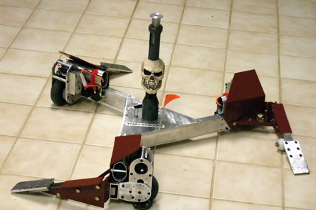
Ready to fight! Grrrrr!
Sept 4th 2007
It's over. We lost in the 30# class.
We're back from DragonCon Robot Battles 2007! Scary-Go-Round did not do well at all. There were two problems. The stage didn't have enough speed bump free space to spin in and the natural gaps between the stage sections caused problems too. But, the major problem was an intermittent loose wire in the controller that put motor #1 in full brake mode most of the time. As a result, the bot spun way too slowly to be effective and the travel-while-spinning mode didn't work. I didn't find out what the problem was until after I got home and did some trouble shooting. If not for the electrical problem The bot would have still lost most of the time but been much more entertaining. I think it might be time to totally abandon this idea forever.
Scary-Go-Round vs Scimitar
All three motors briefly kick in 21 seconds into the video. Too bad they didn't all run all the time.However, my other bot, OmegaForce 2.0 won the 12# class. Click here for details.
Hit Counter = 36890
Previous page: Cube Quest Robot - 2007/8 "The Cubinator"
Next page: Full Body Spinner Experiment
