Six Channel Sonar
by Dale Heatherington
April 2001
While designing my new vacuum robot for the next AHRC Robot Rally I realized I would need a means of measuring the distance between the robot and arena walls if I was to do anything beyond random pattern vacuuming. Sonar seemed to be the most practical technology so I ordered an OEM Polaroid sonar module. There were several problems with this module.
-
Narrow 10 degree beamwidth
-
High cost of $50 per sensor module
-
Long 80ms cycle time
-
Minimum distance is 1.3 feet
-
Makes annoying clicking sounds while operating
-
Poor microcontroller interface
I needed to fully cover the area in front of the 8 inch wide robot to avoid obstacles. The 10 degree beamwidth spec. would require several modules or mechanically rotating a single module. The 80 ms cycle time would require very slow scanning and doom the robot to move at a snails pace. There had to be a better way.
While browsing the Electronic Goldmine catalog I saw two different 40 khz sonar transducers listed. They were only about $1.50 each so I ordered several to experiment with. The part Electronic Goldmine part numbers are G9425 for the Murata MA4053R unit and G2528 for the larger unit.
The G9425 has a 100 degree beamwidth! The G2528s' beamwidth is about 25 degrees. Both have a usable bandwidth of about 4 khz.
I wrote a small test program for the PIC 16C84 and began experimenting with these 40 KHZ transducers. First I tried using a single transducer for transmitting and receiving. I quickly abandoned that idea. The transducers continued to "ring" for a long time after removing the transmit pulse. This required a long receiver blanking time which resulted in a minimum range longer than the Polaroid units! Next I tried using separate transducers for transmit and receive. This worked quite well. Minimum distances of about 6 inches could be measured. With 10 volts peak to peak on the transmitter, objects up to 6 feet away could be detected. The disadvantage is I need two transducers per channel. But they're cheap it's a reasonable tradeoff.
During my experiments I observed that large objects well within sonar range sometimes did not show an echo. Moving them a fraction of an inch resulted in large return echoes. This was caused by multiple reflections arriving at the receiver out of phase. They canceled each other out! The solution is space diversity. Two receiver transducers are placed about an inch apart. They are connected to separate signal processing chains. It's unlikely that both receivers will be in a phase null at the same time so reliably is greatly improved. Now I have three transducers per channel but it works great!
I wanted left and right front sonars to detect objects in the robots path. I needed left and right side sonars so I can do wall following at a specified distance. I also needed left and right rear sonars to align the robot square with a wall after making a 90 or 180 degree turn. This is a total of 6 sonar channels.
Next I needed to work out how to get 6 channels of sonar with the least hardware and software. Driving 6 sonar transmitters from a single PIC chip was easy. I hooked all 6 common leads to one PIC output pin. Each of the other 6 leads went to individual PIC output pins. A total of 7 pins were used. To drive each transducer with 10 volts peak to peak is simple. I simply set the output bit of the desired transducer then use the XOR function to invert all the port bits at 40 khz. The common lead of is always out of phase with the signal lead of the active transducer. All the inactive transducers signal leads follow the common lead so no output is produced from them.
I had to put 330 ohm resistors in series with each transmitter to keep the reactance current spikes from crashing the CPU.
I used two CD4051 8 to 1 analog multiplexers to individually select each pair of receiver transducers. Three PIC output pins are required generate the addresses.
I used a LMC660 quad CMOS op-amp to provide amplification of the returning echoes. There are two channels to handle the receiver transducer pairs. The gain is set at 100.
An LM393 dual comparator is used to detect the presence of echoes. The threshold is dynamically set very high for early echoes and progressively lower for more distant ones. I used a simple RC network to generate the waveform. A pair of pots adjust the overall sensitivity. See figure 1.
The final design uses a PIC 16C73A microcontroller chip for signal processing. Other PIC chips could have been used but I had several 16C73As on hand. The program emits 40 khz pulses (7 cycles in each pulse) on a selected transmitter and then waits for the first echo that exceeds the comparators threshold. It saves the time measured as 38 microsecond intervals in a memory location. Sound travels ½ inch in 38 microseconds. Since we are measuring round trip time every ¼ inch distance increase is 38 microseconds. This provides ¼ inch resolution. The data memory is only 8 bits wide so the maximum value stored is 255. Multiplying 38 microseconds times 255 gives 9.69 milliseconds total time to measure echos. To get cycle time I need to add the 0.9 milliseconds receiver blanking time and transmit pulse time of .175 ms. Total cycle time is 10.77 ms. All 6 channels can be processed in 64.6 milliseconds. 10.77 milliseconds is equal to a distance of 70 inches or 5.8 feet. This the maximum range. The left and right front channels are cycled twice in left-right-right-left order and averaged to remove skew caused by forward motion between samples. See the source code for details.
In addition to conventional sonar, a homing beacon is polled with a 600 microsecond IR pulse. The beacon responds with both IR and a 40 khz sonar pulses. There are three IR pulses emitted from IR LEDs pointed at different angles. A very rough estimate of the relative angle to the beacon can be determined depending on which IR pulses can be seen. The start time of the returned 40 khz sonar pulse is known allowing computation of exact distance from the beacon.
All 6 sonar channels plus the beacon IR and sonar transponder are measured 10 times per second. This includes the double pulsing of the left and right front channels.
The data is transferred out of the processor in 3 wire SPI bus format after all the channels have been processed. See figure 2. The robots main controller reads this data with it's hardware SPI port and the data is transferred to memory in an interrupt routine so there is very little processor overhead. All 9 bytes are transfered in 730 microseconds.
So, how does this system work in practice? Great! The two front sonar channels detect small objects including the legs of "the evil chair". The left and right side sonars provide the distance to the closest wall allowing accurate wall following. The two rear sonars allow the robot to align its rear end at any given angle to the wall. The main limitation is that all objects closer than 6.5 inches read as zero. To follow a wall at zero distance requires a side bump switch.
- Click here to download sonar.zip containing source code and schematic.
- Just the source code
- Just the schematic (A large 228K gif file suitable for printing!)
Figure 1.
Sonar Waveforms
Figure 2.
SPI Bus Waveforms
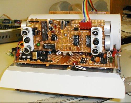
Figure 3.
Sonar board mounted on robot
Front and side transducers visible
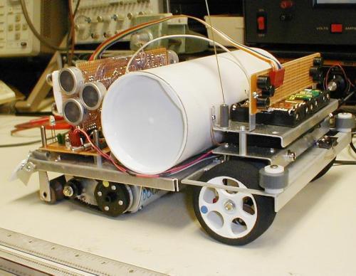
Figure 4.
Side and rear transducers visible
Previous page: Suckmaster II Vacuum Robot
Next page: Delta Force Mini Sumo Robot
